Milling the PCB
This is part 3 in a series. Check out Part 1: Creating a circuit and Part 2: Using KiCAD.
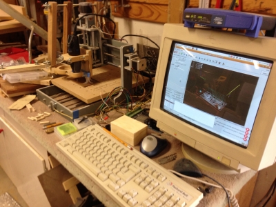
 My CNC setup
Some time ago I bought a small CNC with the intended purpose of using it to make PCBs. While I have used the CNC for lots of things, I have never tried to make a PCB. The amount of work involved in trying to figure out all the different software programs needed, as well as how they work, has made me constantly put it off.
Most of the time I’ve found a way to work around making a PCB, either by permanently mounting a breadboard in a project, using a perfboard and jumpering connections together, or using a pre-made PCB with traces laid out in a sort of breadboard arrangement. More often though, I simply give up on the project.
Since I now have the PCB designed in KiCAD, the next trick is to get it converted so I can mill it on my CNC. KiCAD can't output G-code directly, but it can output Gerber files by using the plot function. To convert the gerber files to G-code there’s a program called pcb2gcode. Surprisingly it was part of the Debian repo so I didn’t need to build it from source. I found a millproject file which was configured to produce Voronoi isolations.
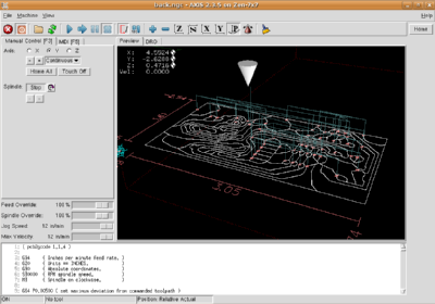
 CNC origin shifted in software
I have the origin on my CNC set to be the lower left, so that X increases to the right and Y increases away from me. The output of pcb2gcode set the origin to the upper left, so that Y increases downward. I found it was much easier to shift the coordinates under Linux CNC than try to figure out how to reposition the output from pcb2gcode.
First two tries came out much too deep. Since it was clear the table wasn't perfectly level, I put another piece of MDF on it and then let the CNC mill a huge flat spot in the center. It took several hours since I only had a tiny 3mm bit. I also found that I needed to slow down the the Z movement when I was zeroing the bit. With it going too fast it often would pierce the copper before seeing the signal. In some cases it would just keep going and I had to e-stop it. With it going about 25mm per second it stopped the instant it made contact with the PCB.
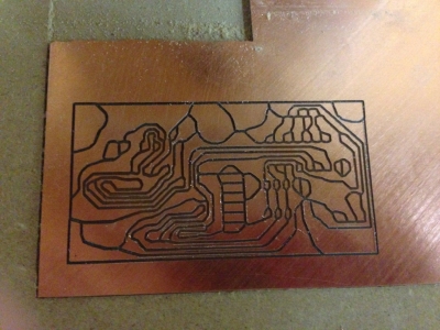
 Looks great!
Third try came out great. The only traces that got lifted were single pads around unused pins. There were a couple of traces that were so thin that I was sure they were broken but they toned out fine with the meter. One thing that was annoying is that the CNC ends up going over each path twice because it goes entirely around each shape. It would be nice if there was a way to make it smarter because it would cut the milling time in half.
Because of limitations with the Linux CNC software, it was easier to drill all the holes with the same size bit. I used a #59 1.041mm bit and then did the large 3mm holes for the D-sub connector brackets on my drill press. The 1.041mm holes were a bit too large though and it made soldering difficult. I ordered some #67 0.813mm bits for next time. I’ll probably split the drill file into 3 parts since I can’t re-zero the tool when it’s stopped at the tool change step.
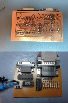
 Soldered up, ready to try
After getting it all soldered up the board mostly worked. I had one short from the blue to red trace and once I scraped off the little bit of solder, it worked exactly like it was supposed to! As a comparison I connected the Commodore 128 to my Sony KV-1311CR monitor which has both CGA/RGBI and analog RGB inputs. The colors are nearly identical in both modes.
What's cool is that the entire process of creating and milling the PCB used only open source software: KiCAD, pcb2gcode, and LinuxCNC/EMC2. I still want to make a couple of changes to the circuit so that I can make it work with 5v or 3v3 depending on the resistor values, but I’m making what I’ve got so far available on github under a Creative Commons license, so it's open too.
My maker skills have definitely leveled up. I have to say being able to finally be able to make my own PCBs feels very powerful. It's very exciting knowing that whenever I need a new little circuit to do something, I don't have to just dream about it, I can actually make it!


+1 Posted by H2Obsession • May.17.2014 at 16.36 • Reply
Nice series of articles. Really interesting using CNC to etch a board! Never heard of that (use chemical etching myself if I want a 'professional look'), but you show that it does work! I like the photos of the hardware, but would really like to see the final results, what the screen looks like.
I noticed ou uused a varieyof resistor values, I'm guessing you played wwiith values to find something you like? How portable do you think that is? I mean would the same values work for a genuine GBS-8220 instead of a clone? How much do you think the monitor itself influences the best choice of resistor values?
I ask because a guy named Ricad42 did something similar, but he had his ownn set of different resistor values. Mind you he was combining Intensity using op-amps instead of a resistor network like you. He said his choices were based on comparison with a C1084 (or was it a C1902?) monitor.
+1 Posted by FozzTexx • May.17.2014 at 17.23 • Reply
If you look through the photo gallery you can see pictures of what the output is. I show it connected both to an LCD monitor through the GBS-8220 and through an old Sony monitor which can do both analog 15khz and CGA, so no GBS-8220 involved. For the resistors I just copied the values that were in the circuit that I found in part 1, although I still need to put in the right value for the brown circuit.
+1 Posted by H2Obsession • May.17.2014 at 21.55 • Reply
Where is the photo gallery? I could not find a link. I also tried the SEARCH function which brought up an article and not an actual photo gallery. Off-topic, I did find your article "Printing posters without graphics" which is pretty cool. I've toyed with generating ASCII art, but never poster-sized :)
+1 Posted by FozzTexx • May.17.2014 at 22.02 • Reply
The photo gallery is right above the comments, right below the article.
+1 Posted by H2Obsession • May.18.2014 at 03.20 • Reply
Thanks, I was wondering what that little empty box was... silly browser. I discovered I can click on thin vertical stripes to open up the images in new window. The Whie Sony monitor olors look pretty good, except for Brown looks very close to dark red and dark gray nearly black. The other Black monitor has nicer Brown and a very destinguished dark gray... but isn't that the one with the GBS-8220 and your circuit? It is amazing your circuit IMPROVES the colors, compared to the Sony.
+1 Posted by Willian Oliveira • Sep.26.2018 at 15.06 • Reply
In the KiCad design the R8 resistor is described as 2K and in the photo of its board it is a 2.2K (2200 ohm). Does it make any difference in color output? Can I use this project for an IBM XT? Would the colors be faithful to the original? Thank you
+1 Posted by FozzTexx • Sep.26.2018 at 15.12 • Reply
The 2.2k is because that was the closest I had and the colors weren't exactly right. The board will work with any CGA output.