
Testing DRAM Using an Arduino
 Bad RAM on the IIgs
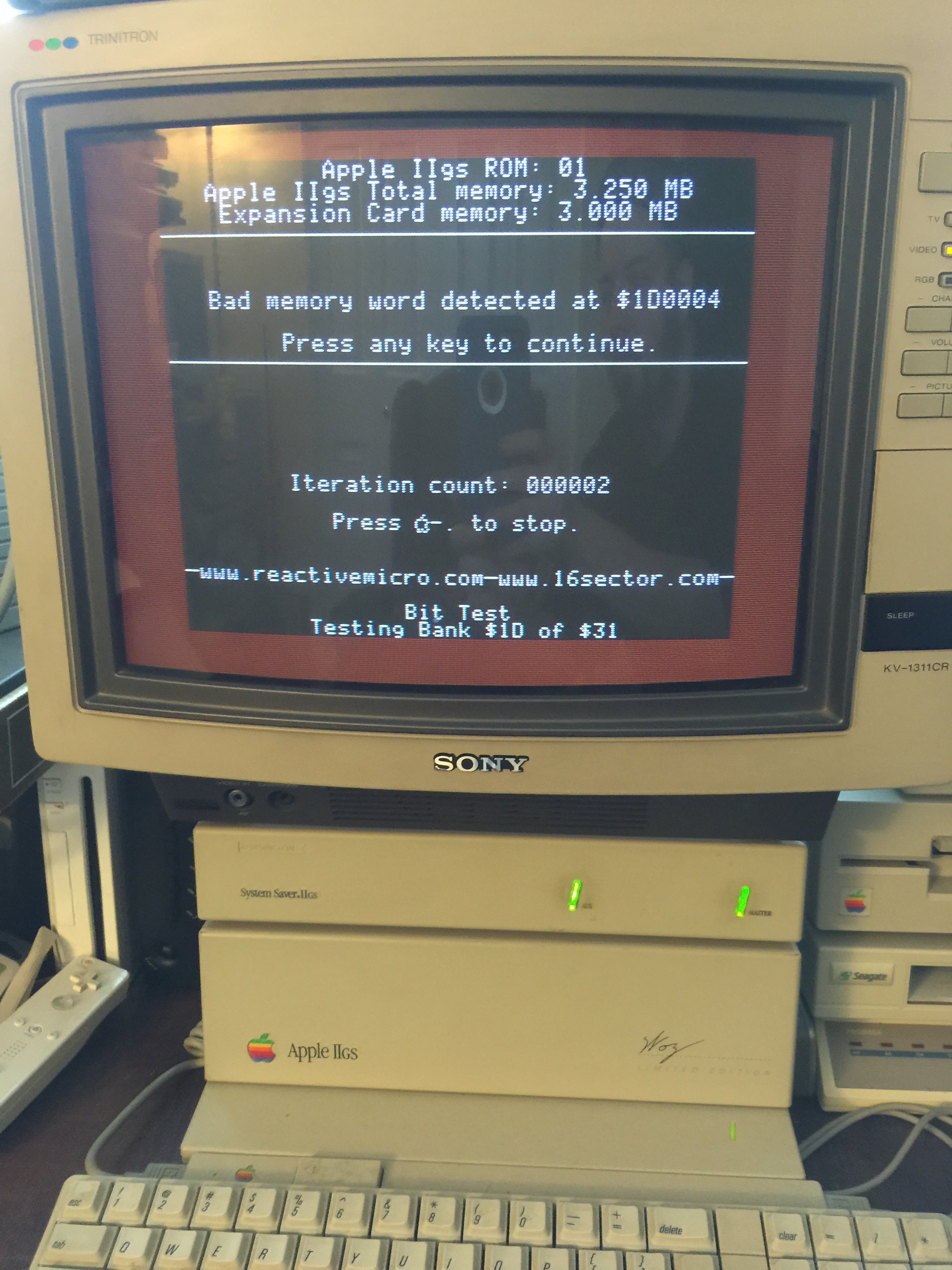
A couple of weekends ago I was in the mood to do some retrogaming and didn’t know what I wanted to play so I asked for some suggestions from Twitter. I played some Castle Wolfenstein, Snake Byte, BC’s Quest for Tires, and Miner 2049er on the Apple IIe and then I wanted to try some games on my Apple IIgs. Unfortunately my IIgs has had intermittent issues for a long time, and it was looking like bad RAM might be the culprit.
Bad RAM on the IIgs
A couple of weekends ago I was in the mood to do some retrogaming and didn’t know what I wanted to play so I asked for some suggestions from Twitter. I played some Castle Wolfenstein, Snake Byte, BC’s Quest for Tires, and Miner 2049er on the Apple IIe and then I wanted to try some games on my Apple IIgs. Unfortunately my IIgs has had intermittent issues for a long time, and it was looking like bad RAM might be the culprit.
The IIgs has an Applied Engineering GS~RAM Plus in it with 3 megabytes of RAM. The RAM is divided up into 1 meg banks, and each bank is made of eight 1M x 1 DRAM chips. I figured if I could narrow down which chip was bad I could replace it or the entire bank. There are lots of different makes of DRAM chips which are compatible, Hitachi labels theirs HM511000 & HM511001, OKI has MSM411000RS & MSM411001RS, and NEC has D421000C & D421001C. As it turned out an old ISA RAM card I got from a garage sale a year or two ago was filled with Toshiba TC511001 chips so I had plenty of spares.
My first thought was to test the chips in the TL866CS, but it doesn’t support them. What to do? Well why not build something with an Arduino to test the DRAM? I wasn’t sure how easy that would be since DRAM is trickier than SRAM because it requires a periodic refresh to keep the bits from fading. Looking around to see if anyone had done such a thing before I found this post where Len Page had done something similar using smaller 256k x 1 chips that were in his PDP 11.
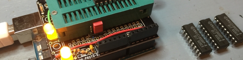
I bought a bunch of Zero Insertion Force (ZIF) sockets a while back thinking I might make some cartridge boards for my Atari 800 or Atari 2600 that would let me easily swap out an EPROM, but of course they had been sitting in one of my electronics parts bins since then. I wasn’t sure how hard it would be to wire up a ZIF socket to an Arduino but then I also discovered I had some proto shields sitting around unused.
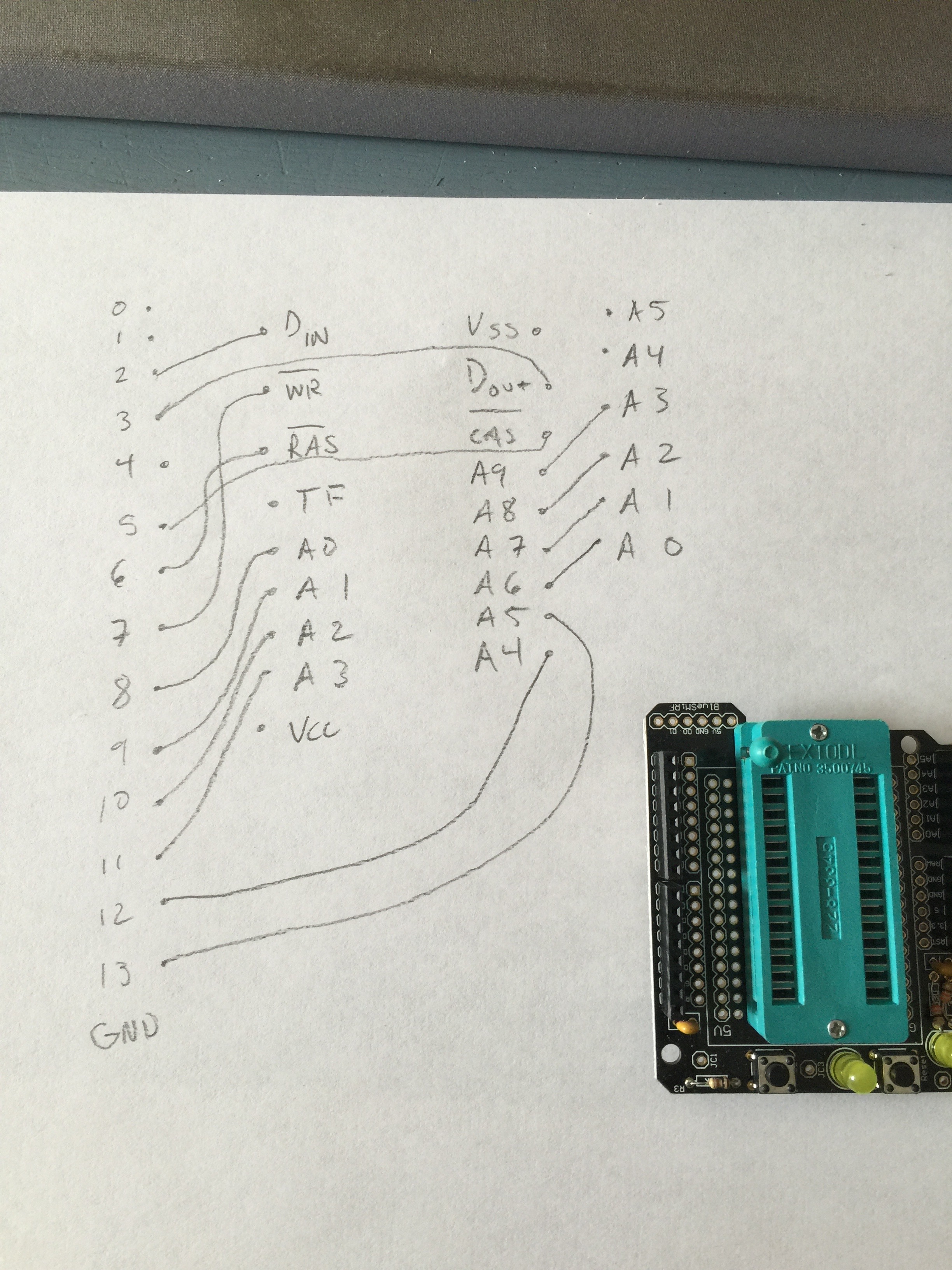 Pinout of DRAM to Arduino
I sketched out how I would need to wire up the DRAM chip to the arduino pins, and it actually looked pretty simple with mostly straight runs. I soldered the ZIF socket onto the shield and then used wire-wrap wire to link everything together. I was going to use regular wire but trying to strip the insulation off such short pieces of wire was a pain and by using wire-wrap wire the soldering iron would just melt the insulation off as I soldered making it very easy to solder the two ends in place and then trim the wire after.
Pinout of DRAM to Arduino
I sketched out how I would need to wire up the DRAM chip to the arduino pins, and it actually looked pretty simple with mostly straight runs. I soldered the ZIF socket onto the shield and then used wire-wrap wire to link everything together. I was going to use regular wire but trying to strip the insulation off such short pieces of wire was a pain and by using wire-wrap wire the soldering iron would just melt the insulation off as I soldered making it very easy to solder the two ends in place and then trim the wire after.
What makes DRAM seem tricky is that it has to be periodically refreshed because it’s made of capacitors. As long as you access each row within the refresh time, the RAM won’t lose data. Reading or writing a row will refresh all the columns in that row, or a separate refresh cycle can be used. CAS before RAS is a timesaving trick to let the chip decide which row to update so that the address lines don’t need to be set. Since my tester would be spending all its time reading and writing I didn’t need to worry about a refresh cycle. It doesn’t take very long to cycle through 1024 rows so keeping the DRAM refreshed is not a problem.
Really the only tricky part is how the address bus is multiplexed. There’s 20 bits of address but only 10 pins which means you load half of the address and latch it, then load the other half.
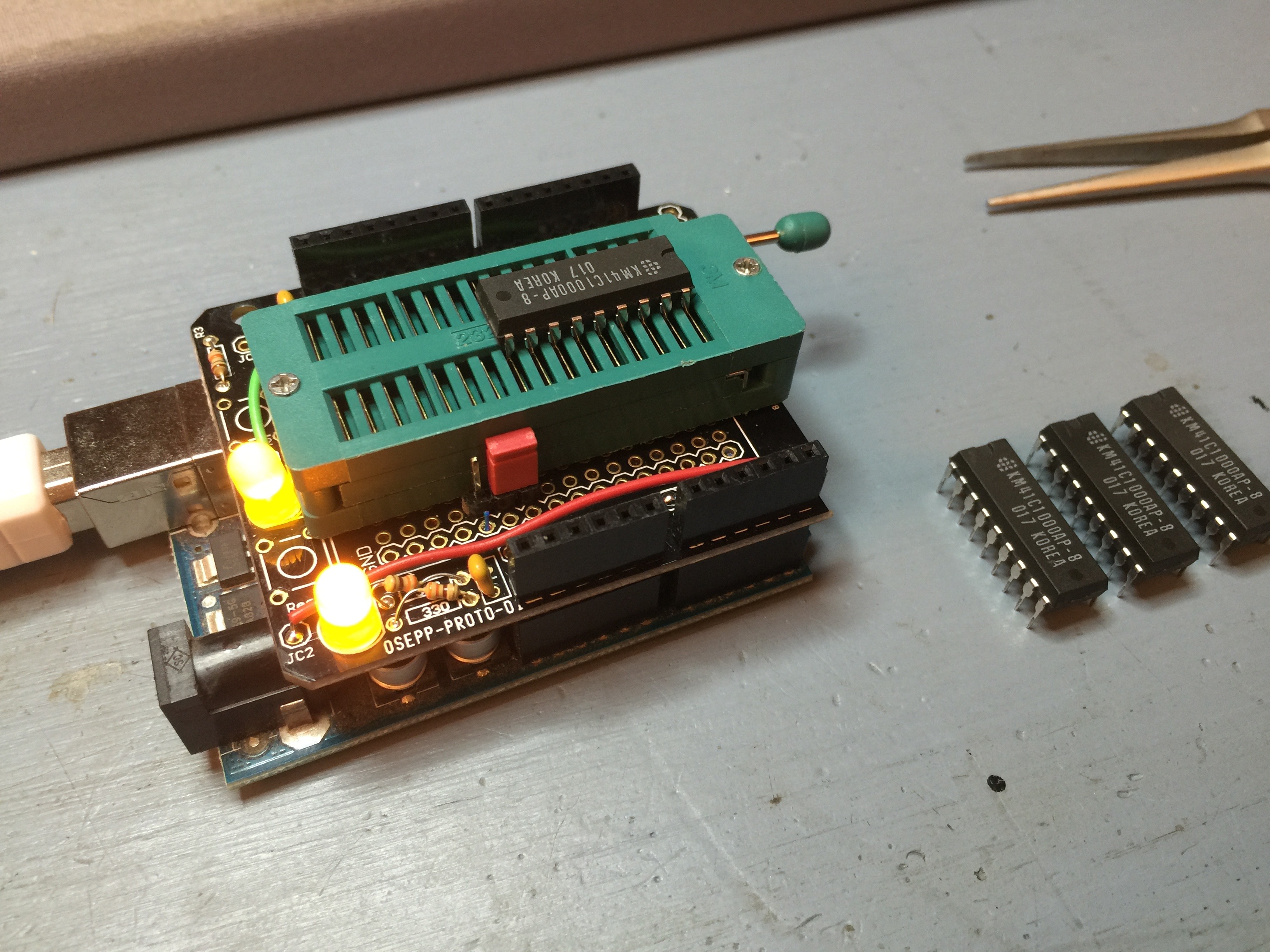 Test passed!
The software on the Arduino is also extremely simple. To test the RAM it was filled with different patterns and then read back to verify if the expected value was there or not. Since the shield happened to have a couple of LEDs on it, I used them to report the status of testing. Surprisingly writing one million bits takes more than a couple of seconds. I was glad I had the LEDs so that I could start the test and walk away and when I returned I could see if it had passed or failed.
Test passed!
The software on the Arduino is also extremely simple. To test the RAM it was filled with different patterns and then read back to verify if the expected value was there or not. Since the shield happened to have a couple of LEDs on it, I used them to report the status of testing. Surprisingly writing one million bits takes more than a couple of seconds. I was glad I had the LEDs so that I could start the test and walk away and when I returned I could see if it had passed or failed.
If you've got some DRAM you need to test and want to use my work as a starting point, I've uploaded the Arduino software and schematic to github.
Unfortunately the problem with the IIgs seems to be not as simple as bad RAM. All 24 chips tested just fine in my Arduino DRAM tester. After putting them back in the IIgs I ran MegaMemoryTest again and on the first try it said the RAM had failed, but when I tried to repeat the test it passed. I’m now wondering if maybe one of the support chips on the GS~RAM Plus is going bad, or if it’s a deeper problem with something on the IIgs motherboard. Hopefully it’s a chip I can replace but I wonder if one of the GALs on the GS~RAM Plus might be failing.
Links:
-

-
Bad RAM on the IIgs
-
Bad RAM on the IIgs
-
Applied Engineering GS~RAM Plus with 3 megs of DRAM
-
ISA card with 8 megs of DRAM
-
Testing a single bank in the IIgs
-
Pinout of DRAM to Arduino
-
Proto shield
-
Had to remove some parts to make the ZIF socket fit
-
Wiring the ZIF socket to the Arduino pins
-
Filed the LED so I could put it back
-
Fully assembled and ready to test
-
Test passed!
-
Chips passed but IIgs still fails
-
2nd try and now it passes?


 Recent Toots
+1 Posted by toybuilder • Mar.15.2016 at 07.32 • Reply
Sometimes. it's not the chips at all, but the supply rail (or the caps on the rails) going bad.
+1 Posted by Dagen • Mar.15.2016 at 16.27 • Reply
I have a more full featured memory testing program that might help. You can also specify which banks to test so it might make it easier to pin down a problem area.
Good luck!
https://github.com/digarok/mmt